Results for Electrical Machines

Industries Extension Officer Synchronous motor mcq part2

March 30, 2019

Industries Extension Officer Synchronous motor mcq part2


11. In a 3-phase synchronous motor
A. the speed of stator MMF is always more than that of rotor MMF
B. the speed of stator MMF is always less than that of rotor MMF.
The speed of stator MMF is synchronous speed while that of
rotor MMF is zero.
D. rotor and stator MMF are stationary with respect to each other


12. A salient pole synchronous motor is running at no load. Its field
current is switched off. The motor will
A. come to stop.
B. continue to run at synchronous speed
C. continue to run at a speed slightly more than the synchronous speed
D. continue to run at a speed slightly less than the synchronous speed


13. Asynchronous motor is called a synchronous capacitor, when it is:
A. under loaded
B. under excited
C. over excited
D. overload


14. The size of a synchronous motor is determined by the its..
A.KVA rating
B. kW rating
C. KVAR rating
D. none of the above


15. The synchronous speed for a 3 phase 6-pole induction motor is 1200
rpm. If the number of poles is now reduced to 4 with the frequency
remaining constant, the rotor speed with a slip of 5% will be.
A. 1690 rpm B.1750 rpm C. 1500 rpm D. 1710 rpm


16. The maximum power for a given excitation in a synchronous motor
is developed when the power angle is equal to
A.
B.45
C. 60
D.90


17. Asynchronous motor delivers reactive power when.....
A. over excited
B. under excited
C. normally excited
D. none of the above


18. In synchronous motor out of the following losses, which one will
have the highest proportion ?
A. stator copper losses
B. friction and windage losses
C. eddy current losses
D. iron losses


19. The capacity of a synchronous capacitor is generally in the range of
A. VAR B.MVAR C .KVAR D. none of the above


20.
The cost of leading power factor synchronous motor is. .. unity
power factor motors
B. more than
A. less than
C. about the same
D. none of the above
Industries Extension Officer Synchronous motor mcq part2 Industries Extension Officer Synchronous motor mcq part2 Reviewed by Sikha on March 30, 2019 Rating: 5

Industries Extension Officer Synchronous Motors MCQs

March 30, 2019

SYNCHRONOUS MOTORS


11.A three phase synchronous motor will have:
A.no slip rings
B. three slip rings
C. four slip rings
D. two slip rings

2.When a synchronous motor is running at synchronous speed, the
damper winding produces
A. damping torque
B. eddy current torque
C. torque aiding the developed torque. 
D. no torque

3. A motor which can conveniently be operated at lagging as well as leading power factors is the
A. squirrel cage induction motor. 
B. wound rotor induction motor
C. synchronous motor
D. DC shunt motor


5. The max'm speed of a synchronous motor in India is:
A. 1500 rpm. B. 1000 r.p.m C. 750 rpm. D.3000 rpm.
The rotor of a synchronous motor is excited with DC when the motor
A. is at standstill 
B. approaches synchronous speed
C. approaches half synchronous speed 
D. none of the above


6. KW rating of synchronous motor exciter is about ....% of the KVA rating of synchronous motor
A. 3
B.
SEC. 10
D. 15

7.
Synchronous speed of an induction motor is always:
A. equal to rotor speed
B. greater than rotor speed
C. twice the rotor speed
D. less than rotor speed

8.
Synchronous speed of an induction motor is 1000 rpm.
What will be the rotor speed, if slip is 3%
A. 30 rpm
B.300 rpm. C. 1700 rpm D.970 rpm


9Asynchronous motor, connected to an infinite bus is working at
leading p.f. It's excitation is
A. less than supply voltage Vs
B. equal to Vs
C.> Vs
D. none of these

10. Synchronizing power comes into play when the rotor speed is
A. equal to Synchronous speed Ns
C. SNs
D. either more
Industries Extension Officer Synchronous Motors MCQs Industries Extension Officer Synchronous Motors MCQs Reviewed by Sikha on March 30, 2019 Rating: 5

Synchronous Motor- Advantages, disadvantages and applications

August 13, 2017
Synchronous Motor- Advantages, disadvantages and applications

Advantages:
1.     Its power factor can be controlled by the control of field current.
2.     In certain applications, the fact that its speed is independent of load and applied voltage, may be important.
3.     It’s efficiency is slightly higher than that of induction motor.
4.     For low speeds and high rating, ( above 500 kW) a synchronous motor is cheaper than induction motor

Disadvantages:
1.     The need of dc source for excitation (usually a an exciter is mounted on the shaft to provide the excitation)
2.     Need of starting and synchronizing
3.     Instability
4.     Hunting
5.     Need of expensive control devices


In view of the above advantages, and  disadvantages, the synchronous motors are used only for low speed, high up speed, high hp requirements.

Applications:

1.     Large low head pumps
2.     Rubber mills and mixers
3.     Crushers
4.     Paper mill drives
5.     Compressors
6.     Rolling mills
7.     Ball mills etc
8.     Synchronous motor can also be used as a phase modifier for voltage regulation of transmission lines.


Synchronous Motor- Advantages, disadvantages and applications Synchronous Motor- Advantages, disadvantages and applications Reviewed by Sikha on August 13, 2017 Rating: 5

SHORT CIRCUIT CHARACTERISTICS OF AN ALTERNATOR

January 18, 2016
The three terminals of the armature are short circuited .


The machine is driven at approximately synchronous rated speed and measurements of armature short circuit currents are made for various values of field currents usually up to and above rated armature current.


In conventional synchronous machines the short circuit characteristics is practically linear because the iron is unsaturated up to rated armature current
SHORT CIRCUIT CHARACTERISTICS OF AN ALTERNATOR SHORT CIRCUIT CHARACTERISTICS OF AN ALTERNATOR Reviewed by Sikha on January 18, 2016 Rating: 5

Open Circuit Characteristics (OCC) of an Alternator

January 18, 2016
To obtain the open circuit characteristics the machine is driven at rated speed without the load. Readings of the line-to-line voltage are taken for various values of field current. The voltage, except in very low voltage machines, is stepped down by the means of a potential transformer.

Experimental set up-


OCC


If not for the magnetic saturation of the iron, the open circuit characteristics would be linear as represented by the air gap line.


Open Circuit Characteristics (OCC) of an Alternator Open Circuit Characteristics (OCC)  of an Alternator Reviewed by Sikha on January 18, 2016 Rating: 5

Three phase alternator

January 18, 2016

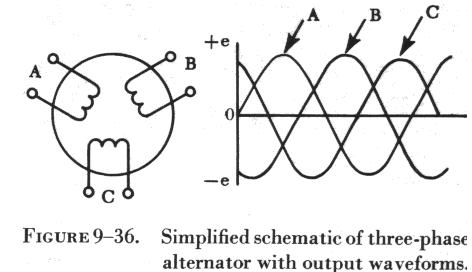
The three-phase alternator has three single-phase windings spaced so that the voltage induced in any one is phase-displaced by 120 degrees from the other two.
The voltage waveforms generated across each phase are drawn on a graph phase-displaced 120 degrees from each other.
The three phases are independent of each other.
•One point from each winding can be connected to form a  neutral and thus make a wye connection.
•The voltage from this point to any one of the line leads will be the phase voltage. The line voltage across any two line leads is the vector sum of the individual phase voltages. The line voltage is 1.73, (Ö3 ), times the phase voltage.
Since the windings form only one path for current flow between phases, the line and phase currents are equal.
A three-phase stator can also be connected so that the phases form a “delta” connection.
•In the delta connection the line voltages are equal to the phase voltages, but the line currents will be equal to the vector sum of the phase currents.
•Since the phases are 120 degrees out of phase, the line current will be 1.73, (Ö3 ), times the phase current. Both "wye" and the "delta" connections are used in alternators.
•The frequency of the AC generated by an alternator depends upon the number of poles and the speed of the rotor.
•When a rotor has rotated through an angle so that two adjacent rotor poles (a north and a south) have passed one winding, the voltage induced in that one winding will have varied through a complete cycle of 360 electrical degrees.
•A two pole machine must rotate at twice the speed of a four-pole machine to generate the same frequency.
The magnitude of the voltage generated by an alternator can be varied by adjusting the current on the rotor which changes the strength of the magnetic field.
•A two pole alternator produces one electrical cycle for each complete mechanical rotation.
A four pole alternator will produce two electrical cycles for each mechanical rotation because two north and two south poles move by each winding on the stator for one complete revolution of the rotor.
f = (nRotor)(p/2)/60 = (nRotorp)/120
where   nRotor is the speed of the rotor in revolutions per minute,
  p is the number of poles
  f is the electrical line frequency produced by the alternator.
In an alternator the output voltage varies with the load.
•There are two voltage drops.{ IR & IXL }
•The IXL drop is due to the inductive reactance of the armature windings.
Both the IR drop and the IXL drop decrease the output voltage as the load increases.
•The change in voltage from no-load to full-load is called the “voltage regulation” of an alternator.
•A constant voltage output from an alternator is maintained by varying the field strength as required by changes in load.

Three phase alternator Three phase alternator Reviewed by Sikha on January 18, 2016 Rating: 5

Single phase alternator

January 18, 2016


The two poles of the stator winding are connected to each other so that the AC voltages are in phase, so they add.As the rotor (field) turns, its poles will induce AC voltages in the stator (armature) windings. Since one rotor pole is in the same position relative to a stator pole as any other rotor pole, both the stator poles are cut by equal amounts of magnetic lines of force at any time. As a result, the voltages induced in the two poles of the stator winding have the same amplitude or value at any given instant. 

Single phase alternator Single phase alternator Reviewed by Sikha on January 18, 2016 Rating: 5

Electrical Degree and Mechanical degree in Synchronous machines

January 18, 2016
Angle in Electrical and Mechanical Units

Consider a synchronous machine with two magnetic poles. The idealized radial distribution of the air gap flux density is sinusoidal along the air gap. When the rotor rotates for one revolution, the induced emf, which is also sinusoidal, varies for one cycle as illustrated by the waveforms in the diagram below. If we measure the rotor position by physical or mechanical degrees or radians and the phase angles of the flux density and emf
by electrical degrees or radians, in this case, it is ready to see that the angle measured in mechanical degrees or radians is equal to that measured in electrical degrees or radians, 
i.e.
                                           Î¸=θm
where Î¸   is the angle in electrical degrees or radians and θm   the mechanical angle.
Electrical Degree and Mechanical degree in Synchronous machines Electrical Degree and Mechanical degree in Synchronous machines Reviewed by Sikha on January 18, 2016 Rating: 5

Construction of Synchronous Machines

January 18, 2016

Stator and Rotor

The armature winding of a conventional synchronous machine is almost invariably on the stator and is usually a three phase winding. The field winding is usually on the rotor and excited by dc current, or permanent magnets. The dc power supply required for excitation usually is supplied through a dc generator known as exciter, which is often mounted on the same shaft as the synchronous machine. Various excitation systems using ac exciter and solid state rectifiers are used with large turbine generators.
    There are two types of rotor structures: round or cylindrical rotor and salient pole rotor as illustrated schematically in the diagram below. 
1- Non salient pole , 2- Salient pole 


Generally, round rotor structure is used for high-speed synchronous machines, such as steam turbine generators, while salient pole structure is used for low-speed applications, such as hydroelectric generators. The pictures below show the stator and rotor of a hydroelectric generator and the rotor of a turbine generator.


Construction of Synchronous Machines Construction of Synchronous Machines Reviewed by Sikha on January 18, 2016 Rating: 5

Synchronous Machines

January 18, 2016

1 Introduction
With the development of the technology and the way in which human labour is get-ting minimized and the comforts increasing tremendously the use of electrical energy is ever increasing. Basically electric power is the main source of energy for carrying out many func-tions, as it is a clean and efficient energy source, which can be easily transmitted over long distances. With the availability of Transformer for changing the voltage levels to a very high value (of say 132kV to 400kV) the use of AC power has increased rapidly and the DC power is used only at remote places where AC power cannot be supplied through power lines or cables or for a few social purposes. A synchronous generator is an electrical machine producing alternating emf (Elec- tromotive force or voltage) of constant frequency. In our country the standard commercial frequency of AC supply is 50 Hz. In U.S.A. and a few other countries the frequency is 60 Hz. The AC voltages generated may be single phase or 3-phase depending on the power supplied. For low power applications single phase generators are preferable. The basic prin- ciples involved in the production of emf and the constructional details of the generators are discussed below.

1.1 Generation of emf

In 1831 Faraday discovered that an emf can be induced (or generated) due to relative motion between a magnetic field and a conductor of electricity. This voltage was termed as the induced emf since the emf is produced only due to motion between the conductor and the magnetic field without actual physical contact between them. The principle of electromagnetic induction is best understood by referring to Fig. 1. The magnetic field is produced by the two fixed poles one being the north pole from which the magnetic flux lines emerge and enter into the other pole known as the south pole. It was found that the magnitude of the voltage induced in the conductor is proportional to the rate of change of flux lines linking the conductor.
Synchronous Machines Synchronous Machines Reviewed by Sikha on January 18, 2016 Rating: 5

D.C Machines

July 03, 2013


An electrical machine is an electromechanical energy conversion device. The device which converts electrical energy in to mechanical energy is called a motor. The device which converts mechanical energy in to electrical energy is called a generator.
Classification of electrical machines
           

D.C generator
            D.C generator is a machine which converts mechanical energy in to electrical energy. Direct –current generators are used to supply  power for radio equipment, for battery charging
for electrolytic cells etc. a disadvantage common to all d.c machines is the complexity of design, mainly due to the usage of brushgear. This brush gear can also cause sparking.
            A d.c machine consists essentially a stationary part, called the field structure and a rotating part called, the armature.
Principle of operation:
            D.C generator is based on the principle that whenever magnetic flux is cut by a moving conductor, an e.m.f is induced in the conductor as per Faraday’s laws of electromagnetic induction. The e.m.f so induced is an alternating e.m.f. it is made unidirectional with the help of commutator and brushes. This e.m.f causes the flow of current in the external circuit if the circuit is closed.
            The direction of induced e.m.f is given by Fleming’s right hand rule. Stretch out the right hand with first finger, middle finger and thumb mutually perpendicular to each other. If the first finger points in the direction of flux, and thumb in the direction of motion of the conductor, then the middle finger will point in the direction of the induced e.m.f..

Constructional details:-
            The main parts of a d.c machine (a generator or a motor) are described below.

1)      Yoke:-
It is the outermost cylindrical part of the machine. The yoke is made of cast iron or cast steel or forged steel. The yoke acts as the supporting frame for the machine and also completes the path of the main magnetic flux. In small d.c machines, yoke is made up of cast iron. In large d.c generators, the yoke is made of cast steel from the consideration of better magnetic properties.
2)      Poles:-
The pole consists of pole core and pole shoe. The field coil is wound on the pole core. The poles are made of cast steel or forged steel. In some machines, poles are made from laminated sheet steel. The main functios of the pole shoe are (a) it supports the field coil. (b) it spreads out the magnetic flux in the air gap. (since pole shoe is of large cross section, it reduces the reluctance of the magnetic path.
3)      Field coils:-
The field coils are wound on pole cores. They are connected in series and the connections are arranged so that due to the flow of current in these coils alternate N and S poles are made. The field coils are made from enameled copper wire.
4)      Armature:-
The armature is that part of the d.c machine where an e.m.f is induced as it rotates relative to the main field. The armature consists of the toothed core, a winding dropped in the core slots, and a commutator mouted on the armature shaft. The armature core is composed of silicon- steel laminations. The armature winding consists of sections or coils.
5)      Commutator:-
The commutator, which is a typical component of d.c machines, is a hollow cylinder. The commutator is made up of wedge shaped segments of hogh conductivity hard drawn or copper forged copper. The segments are insulated from each other by thin layer of mica. The function of the commutator is to convert the e.m.f induced in the armature conductors in to unidirectional voltage across the load impedance.


6)      Brushes:-
      The function of the brush is to collect current from the rotating commutator and deliver it to the external load impedance. The brushes are made of carbon. The brushes are mounted in a box type of brush holder and are held on the commutator by a spring.
Simple d.c generator


The fig. gives the basic structure. When a coil is rotated in a uniform magnetic field, an alternating emf is generated across the terminals 1 and 2 of the coil. If a unidirectional current is desired in the external circuit, the two ends of the coil ABCD are connected to the two segments C1 and C2 which are insulated from each other. When C1 is positive, the brush B1 makes contact with it. But for the other half rotation, of the coil, the segment C2 becomes positive and now this makes contact with the brush B2. Thus, we see that the brush remains positive all the time, and hence a unidirectional current results in the external circuit as shown below.


The current in the external circuit is unidirectional. But its strength varies considerably. It raises and falls between zero and maximum for each half rotation of the coil. This defect of having large variations in the unidirectional e.m.f (or current) can be overcome by having more coils on the rotor.


Types of D.C generator:-


D.C generators are generally classified according to the method used for field excitation. Thus, they can be classified as
1.      Separately excited generator
2.      Self excited generator


D.C Machines D.C Machines Reviewed by Sikha on July 03, 2013 Rating: 5

Google

Powered by Blogger.