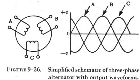
The three-phase alternator has three single-phase windings spaced so that the voltage induced in any one is phase-displaced by 120 degrees from the other two.
The voltage waveforms generated across each phase are drawn on a graph phase-displaced 120 degrees from each other.
•The three phases are independent of each other.
•One point from each winding can be connected to form a neutral and thus make a wye connection.
•The voltage from this point to any one of the line leads will be the phase voltage. The line voltage across any two line leads is the vector sum of the individual phase voltages. The line voltage is 1.73, (Ö3 ), times the phase voltage.
Since the windings form only one path for current flow between phases, the line and phase currents are equal.
A three-phase stator can also be connected so that the phases form a “delta” connection.
•In the delta connection the line voltages are equal to the phase voltages, but the line currents will be equal to the vector sum of the phase currents.
•
•Since the phases are 120 degrees out of phase, the line current will be 1.73, (Ö3 ), times the phase current. Both "wye" and the "delta" connections are used in alternators.
•The frequency of the AC generated by an alternator depends upon the number of poles and the speed of the rotor.
•When a rotor has rotated through an angle so that two adjacent rotor poles (a north and a south) have passed one winding, the voltage induced in that one winding will have varied through a complete cycle of 360 electrical degrees.
•A two pole machine must rotate at twice the speed of a four-pole machine to generate the same frequency.
The magnitude of the voltage generated by an alternator can be varied by adjusting the current on the rotor which changes the strength of the magnetic field.
•A two pole alternator produces one electrical cycle for each complete mechanical rotation.
A four pole alternator will produce two electrical cycles for each mechanical rotation because two north and two south poles move by each winding on the stator for one complete revolution of the rotor.
f = (nRotor)(p/2)/60 = (nRotorp)/120
where nRotor is the speed of the rotor in revolutions per minute,
p is the number of poles
f is the electrical line frequency produced by the alternator.
In an alternator the output voltage varies with the load.
•There are two voltage drops.{ IR & IXL }
•The IXL drop is due to the inductive reactance of the armature windings.
Both the IR drop and the IXL drop decrease the output voltage as the load increases.
•The change in voltage from no-load to full-load is called the “voltage regulation” of an alternator.
•A constant voltage output from an alternator is maintained by varying the field strength as required by changes in load.
Three phase alternator
![Three phase alternator]() Reviewed by Sikha
on
January 18, 2016
Rating:
Reviewed by Sikha
on
January 18, 2016
Rating:


No comments:
Post a Comment