Signals and Systems Notes-1

January 18, 2016
What is Signal?
Signal is a time varying physical phenomenon which is intended to convey information.
OR
Signal is a function of time.
OR
Signal is a function of one or more independent variables, which contain some information.
Example: voice signal, video signal, signals on telephone wires etc.
Note: Noise is also a signal, but the information conveyed by noise is unwanted hence it is considered as undesirable
What is System?
System is a device or combination of devices, which can operate on signals and produces corresponding response. Input to a system is called as excitation and output from it is called as response.
For one or more inputs, the system can have one or more outputs.
Example: Communication System
white'>Signal is a function of one or more independent variables, which contain some information.

Example: voice signal, video signal, signals on telephone wires etc.
Note: Noise is also a signal, but the information conveyed by noise is unwanted hence it is considered as undesirable

Signals and Systems Notes-1 Signals and Systems Notes-1 Reviewed by Sikha on January 18, 2016 Rating: 5

SHORT CIRCUIT CHARACTERISTICS OF AN ALTERNATOR

January 18, 2016
The three terminals of the armature are short circuited .


The machine is driven at approximately synchronous rated speed and measurements of armature short circuit currents are made for various values of field currents usually up to and above rated armature current.


In conventional synchronous machines the short circuit characteristics is practically linear because the iron is unsaturated up to rated armature current
SHORT CIRCUIT CHARACTERISTICS OF AN ALTERNATOR SHORT CIRCUIT CHARACTERISTICS OF AN ALTERNATOR Reviewed by Sikha on January 18, 2016 Rating: 5

Open Circuit Characteristics (OCC) of an Alternator

January 18, 2016
To obtain the open circuit characteristics the machine is driven at rated speed without the load. Readings of the line-to-line voltage are taken for various values of field current. The voltage, except in very low voltage machines, is stepped down by the means of a potential transformer.

Experimental set up-


OCC


If not for the magnetic saturation of the iron, the open circuit characteristics would be linear as represented by the air gap line.


Open Circuit Characteristics (OCC) of an Alternator Open Circuit Characteristics (OCC)  of an Alternator Reviewed by Sikha on January 18, 2016 Rating: 5

Three phase alternator

January 18, 2016

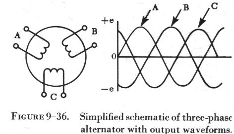
The three-phase alternator has three single-phase windings spaced so that the voltage induced in any one is phase-displaced by 120 degrees from the other two.
The voltage waveforms generated across each phase are drawn on a graph phase-displaced 120 degrees from each other.
The three phases are independent of each other.
•One point from each winding can be connected to form a  neutral and thus make a wye connection.
•The voltage from this point to any one of the line leads will be the phase voltage. The line voltage across any two line leads is the vector sum of the individual phase voltages. The line voltage is 1.73, (Ö3 ), times the phase voltage.
Since the windings form only one path for current flow between phases, the line and phase currents are equal.
A three-phase stator can also be connected so that the phases form a “delta” connection.
•In the delta connection the line voltages are equal to the phase voltages, but the line currents will be equal to the vector sum of the phase currents.
•Since the phases are 120 degrees out of phase, the line current will be 1.73, (Ö3 ), times the phase current. Both "wye" and the "delta" connections are used in alternators.
•The frequency of the AC generated by an alternator depends upon the number of poles and the speed of the rotor.
•When a rotor has rotated through an angle so that two adjacent rotor poles (a north and a south) have passed one winding, the voltage induced in that one winding will have varied through a complete cycle of 360 electrical degrees.
•A two pole machine must rotate at twice the speed of a four-pole machine to generate the same frequency.
The magnitude of the voltage generated by an alternator can be varied by adjusting the current on the rotor which changes the strength of the magnetic field.
•A two pole alternator produces one electrical cycle for each complete mechanical rotation.
A four pole alternator will produce two electrical cycles for each mechanical rotation because two north and two south poles move by each winding on the stator for one complete revolution of the rotor.
f = (nRotor)(p/2)/60 = (nRotorp)/120
where   nRotor is the speed of the rotor in revolutions per minute,
  p is the number of poles
  f is the electrical line frequency produced by the alternator.
In an alternator the output voltage varies with the load.
•There are two voltage drops.{ IR & IXL }
•The IXL drop is due to the inductive reactance of the armature windings.
Both the IR drop and the IXL drop decrease the output voltage as the load increases.
•The change in voltage from no-load to full-load is called the “voltage regulation” of an alternator.
•A constant voltage output from an alternator is maintained by varying the field strength as required by changes in load.

Three phase alternator Three phase alternator Reviewed by Sikha on January 18, 2016 Rating: 5

Single phase alternator

January 18, 2016


The two poles of the stator winding are connected to each other so that the AC voltages are in phase, so they add.As the rotor (field) turns, its poles will induce AC voltages in the stator (armature) windings. Since one rotor pole is in the same position relative to a stator pole as any other rotor pole, both the stator poles are cut by equal amounts of magnetic lines of force at any time. As a result, the voltages induced in the two poles of the stator winding have the same amplitude or value at any given instant. 

Single phase alternator Single phase alternator Reviewed by Sikha on January 18, 2016 Rating: 5

Electrical Degree and Mechanical degree in Synchronous machines

January 18, 2016
Angle in Electrical and Mechanical Units

Consider a synchronous machine with two magnetic poles. The idealized radial distribution of the air gap flux density is sinusoidal along the air gap. When the rotor rotates for one revolution, the induced emf, which is also sinusoidal, varies for one cycle as illustrated by the waveforms in the diagram below. If we measure the rotor position by physical or mechanical degrees or radians and the phase angles of the flux density and emf
by electrical degrees or radians, in this case, it is ready to see that the angle measured in mechanical degrees or radians is equal to that measured in electrical degrees or radians, 
i.e.
                                           Î¸=θm
where Î¸   is the angle in electrical degrees or radians and θm   the mechanical angle.
Electrical Degree and Mechanical degree in Synchronous machines Electrical Degree and Mechanical degree in Synchronous machines Reviewed by Sikha on January 18, 2016 Rating: 5

Construction of Synchronous Machines

January 18, 2016

Stator and Rotor

The armature winding of a conventional synchronous machine is almost invariably on the stator and is usually a three phase winding. The field winding is usually on the rotor and excited by dc current, or permanent magnets. The dc power supply required for excitation usually is supplied through a dc generator known as exciter, which is often mounted on the same shaft as the synchronous machine. Various excitation systems using ac exciter and solid state rectifiers are used with large turbine generators.
    There are two types of rotor structures: round or cylindrical rotor and salient pole rotor as illustrated schematically in the diagram below. 
1- Non salient pole , 2- Salient pole 


Generally, round rotor structure is used for high-speed synchronous machines, such as steam turbine generators, while salient pole structure is used for low-speed applications, such as hydroelectric generators. The pictures below show the stator and rotor of a hydroelectric generator and the rotor of a turbine generator.


Construction of Synchronous Machines Construction of Synchronous Machines Reviewed by Sikha on January 18, 2016 Rating: 5

Synchronous Machines

January 18, 2016

1 Introduction
With the development of the technology and the way in which human labour is get-ting minimized and the comforts increasing tremendously the use of electrical energy is ever increasing. Basically electric power is the main source of energy for carrying out many func-tions, as it is a clean and efficient energy source, which can be easily transmitted over long distances. With the availability of Transformer for changing the voltage levels to a very high value (of say 132kV to 400kV) the use of AC power has increased rapidly and the DC power is used only at remote places where AC power cannot be supplied through power lines or cables or for a few social purposes. A synchronous generator is an electrical machine producing alternating emf (Elec- tromotive force or voltage) of constant frequency. In our country the standard commercial frequency of AC supply is 50 Hz. In U.S.A. and a few other countries the frequency is 60 Hz. The AC voltages generated may be single phase or 3-phase depending on the power supplied. For low power applications single phase generators are preferable. The basic prin- ciples involved in the production of emf and the constructional details of the generators are discussed below.

1.1 Generation of emf

In 1831 Faraday discovered that an emf can be induced (or generated) due to relative motion between a magnetic field and a conductor of electricity. This voltage was termed as the induced emf since the emf is produced only due to motion between the conductor and the magnetic field without actual physical contact between them. The principle of electromagnetic induction is best understood by referring to Fig. 1. The magnetic field is produced by the two fixed poles one being the north pole from which the magnetic flux lines emerge and enter into the other pole known as the south pole. It was found that the magnitude of the voltage induced in the conductor is proportional to the rate of change of flux lines linking the conductor.
Synchronous Machines Synchronous Machines Reviewed by Sikha on January 18, 2016 Rating: 5

Electrical Machines solved Questions-Gate 2016

January 18, 2016
MCQ 4.1 The slip of an induction motor normally does not depend on
(A) rotor speed (B) synchronous speed
(C) shaft torque (D) core-loss component

MCQ 4.2 A 220 V, 15 kW, 100 rpm shunt motor with armature resistance of 0.25 Ω,
has a rated line current of 68 A and a rated field current of 2.2 A. The
change in field flux required to obtain a speed of 1600 rpm while drawing a
line current of 52.8 A and a field current of 1.8 A is
(A) 18.18% increase (B) 18.18% decrease
(C) 36.36% increase (D) 36.36% decrease

MCQ 4.3 The locked rotor current in a 3-phase, star connected 15 kW, 4 pole, 230 V, 50 Hz induction motor at rated conditions is 50 A. Neglecting losses and magnetizing current, the approximate locked rotor line current drawn when the motor is connected to a 236 V, 57 Hz supply is
(A) 58.5 A (B) 45.0 A
(C) 42.7 A (D) 55.6 A

MCQ 4.4 A single phase 10 kVA, 50 Hz transformer with 1 kV primary winding draws 0.5 A and 55W, at rated voltage and frequency, on no load. A second transformer has a core with all its linear dimensions 2 times the corresponding dimensions of the first transformer. The core material and lamination thickness are the same in both transformer. The primary winding of both the transformers have the save number of turns. If a rate voltage of 2 kV at 50 Hz is applied to the primary of the second transformer, then the no load current and power, respectively, are
(A) 0.7 A, 77.8 A (B) 0.7 A, 155.6W
(C) 1A, 110W (D) 1A, 220W

MCQ 4.5 A 4 point starter is used to start and control the speed of a
(A) dc shunt motor with armature resistance control
(B) dc shunt motor with field weakening control
(C) dc series motor
(D) dc compound motor


                                                                      ANSWERS


Answers will be updated soon....
Electrical Machines solved Questions-Gate 2016 Electrical Machines solved Questions-Gate 2016 Reviewed by Sikha on January 18, 2016 Rating: 5

Gate 2016 preparation-Signals and Systems

January 01, 2016
·         Continuous and Discrete Time Signals
  • We  need to study here the impact of shifting and scaling operations on the waveform of the signals, Refer in  in Oppenheim book.
  •  classifications of signals based on different criteria like:
a)      Periodic and Aperiodic Signal
b)      Even and Odd Signal
c)      Power and Energy Signals


  • Linear Time Invariant Systems
This is the most important part in Signals and Systems .
  • impulse response -The impulse response is useful when there is a connection of more than one systems like  in cascade configuration or parallel one but you need to remember the equivalent impulse response of thesystem.
  • convolution methodology
by the help of convolution we can compute output at some points only and verify with the options given and save time.
  • properties of Systems like
a)      Causality,
b)      Time-Invariance,
c)       Stability,
d)     Linearity
e)      and we need to study the criterion to determine each of these properties for a system
  • Fourier Series
  • two types of Fourier Series and Transforms  for Continuous Time Signals and other for Discrete Time Signals. for EEE GATE course discrete time Fourier Series is not included and hence they only need to prepare only continuous time fourier series.
Need to remember two things or rather three things which are:
  • Analysis and Synthesis Equations
  • Properties of Transforms
  • Common Transform Pairs
Fourier Transform
  • need to remember that Fourier Transform exists for Aperiodic Signals
  • Fourier Series for Periodic Signals
  • Fourier Transform approaches Fourier Series for periodic Signals.

Also, one more important thing is the fourier transform of rectangular and triangular functions and the converse also which can easily be computed using duality property.
Laplace Transform
  • Laplace Transforms only exist for Continuous Time
  • The concept of Region of Convergence (ROC) as the same transform may have different inverses based on different ROCs.
  • no Laplace Transform is complete without
  • the concept of Initial Value and Final Value Theorem
  • Before applying final value theorem, please verify the stability.
Z-Transform
  • Z-Transform is for the discrete time signals
  • some striking differences also like in case of Final Value Theorem
  • the concept of Stability and Causality
  • pole-zero plot is given and system properties need to be identified.
Sampling

  • important concept in Sampling is for the Nyquist Rate and Nyquist Frequency
  • practice drawing one or two waveforms where sampling frequency is less than Nyquist Frequency
  • Band-Pass Sampling Theorem as that may also be asked.
Gate 2016 preparation-Signals and Systems Gate 2016 preparation-Signals and Systems Reviewed by Sikha on January 01, 2016 Rating: 5

Gate Preparation- Power Systems

December 08, 2015
The major topics in Power Systems for Gate 2016 are as follows:
A. Transmission and Distribution
1.     overhead transmission lines 
·           memorize the expressions for Inductance and Capacitance for both Single Phase and Three Phase Lines. 
·          practice some problems based on this which involve the computation of GMD and GMR.
2.      modelling of Short and Medium Transmission Lines 
·         Long Transmission Lines is not much important in Steady State Analysis and Short Transmission Line is most important.
·         A,B,C,D Parameters of the line 
·         power expressions in terms of A,B,C,D 
·         approximate voltage regulation in Short Transmission Line which is same as Transformer.
3.      Surges 
1.        memorize the thevenin equivalent circuit for analysis of surges to calculate the Transmission and Reflection Coefficient for Voltage
2.       Voltage Control and Power Factor Correction
4. UG Cables
1.       insulation resistance
3.       capacitance model for 3 phase  3 core belted cable which has core capacitance and sheath capacitance.

4.      Overhead Insulator
    1.  voltage distribution across different discs can be asked
    2. remember the expression upto 3 discs.

6.       Distribution Systems
    1. applying KVL and finding the currents in different branches.

you can find the Solved question papers of Gate (from 2000 to 2015) Electrical HereGATE - Electrical Engineering 2016 : Solved Papers 2000 - 2015 (English) 13th Edition 
Gate Preparation- Power Systems Gate Preparation- Power Systems Reviewed by Sikha on December 08, 2015 Rating: 5

Picture and Sound reception in TV

December 04, 2015
TV receiver
The receiving antenna intercepts the radiated picture and sound carrier signals and feeds them to the RF tuner . The receiver is of the heterodyne type and employs two or three stages of intermediate frequency (IF) amplification. The output from the last IF stage is demodulated to recover the video signal. This signal that carries the picture information is

amplified and coupled to the picture tube which converts the electrical signal back into picture elements of the same degree of black and white.

 The picture tube shown in Fig. below is very similar to the cathode-ray tube used in an oscilloscope

The glass envelope contains an electron gun structure that produces a beam of electrons aimed at the fluorescent screen. When the Electron beam strikes the screen, light is emitted. The beam is deflected by a pair of deflecting coils mounted on the neck of the picture tube in the same way and rate as the beam scans the target in the camera tube. The  amplitudes of the currents in the horizontal and vertical deflecting coils are so adjusted that the entire screen, called raster, gets illuminated because of the fast rate of scanning.
The video signal is fed to the grid or cathode of the picture tube. When the varying
signal voltage makes the control grid less negative, the beam current is increased, making the
spot of light on the screen brighter. More negative grid voltage reduces the brightness. If the
grid voltages is negative enough to cut-off the electron beam current at the picture tube there
will be no light. This state corresponds to black. Thus the video signal illuminates the fluorescent screen from white to black through various shades of grey depending on its amplitude at any instant. This corresponds to the brightness changes encountered by the electron beam of the camera tube while scanning the picture details element by element. The rate at which the spot of light moves is so fast that the eye is unable to follow it and so a complete picture is seen because of the storage capability of the human eye.
 Sound reception
The path of the sound signal is common with the picture signal from antenna to the video detector section of the receiver. Here the two signals are separated and fed to their respective channels. The frequency modulated audio signal is demodulated after at least one stage of amplification. The audio output from the FM detector is given due amplification before feeding it to the loudspeaker.
Synchronization
It is essential that the same coordinates be scanned at any instant both at the camera tube target plate and at the raster of the picture tube, otherwise, the picture details would split and get distorted. To ensure perfect synchronization between the scene being televised and the picture produced on the raster, synchronizing pulses are transmitted during the retrace, i.e., fly-back intervals of horizontal and vertical motions of the camera scanning beam. Thus, in addition to carrying picture detail, the radiated signal at the transmitter also contains
synchronizing pulses. These pulses which are distinct for horizontal and vertical motion control, are processed at the receiver and fed to the picture tube sweep circuitry thus ensuring that the receiver picture tube beam is in step with the transmitter camera tube beam.
Receiver controls

The front view of a typical monochrome TV receiver, having various controls is shown in Fig. The channel selector switch is used for selecting the desired channel. The fine tuning control is provided for obtaining best picture details in the selected channel. The hold control is used to get a steady picture in case it rolls up or down. The brightness control varies the beam intensity of the picture tube and is set for optimum average brightness of the picture. The contrast control is actually the gain control of the video amplifier. This can be varied to obtain the desired contrast between the white and black contents of the reproduced picture. The volume and tone controls form part of the audio amplifier in the sound section, and are used for setting the volume and tonal quality of the sound output from the loudspeaker
Picture and Sound reception in TV Picture and Sound reception in TV Reviewed by Sikha on December 04, 2015 Rating: 5

Picture transmission in TV -part 2

December 04, 2015

TV transmitter-Block diagram


Picture transmission in TV -part 2 Picture transmission in TV -part 2 Reviewed by Sikha on December 04, 2015 Rating: 5

Google

Powered by Blogger.